Safety Relays Explained: A Guide to How It Works
October 1, 2024 in Machine Safety Blog byEstimated reading time: 11 minutes
Updated April 30, 2025 – Corrections made based on feedback. Thanks to Frank at Automated Machine Technologies for the input.
Updated December 5, 2025 – Additional refinements were made to improve clarity around wiring practices, diagnostic behaviour, and OSSD signal explanations.
Table of contents
Introduction
A safety relay is an electromechanical or electronic device designed to reduce risk and implement safety functions, particularly in industrial environments. Its primary goal is to shut down power and remove risk safely and reliably. It reduces the risk of hazards and decreases the chance of damage, injury, or death.
It’s important to note that a safety relay is not a stand-alone device. Still, we install it as part of a more extensive control and safety circuit inside a machine. It serves as an interface between safety devices and machine components.
Unlike regular relays, we build safety relays to meet stringent safety standards, incorporating fail-safe principles that guarantee operational safety in critical conditions. A safety relay helps detect failures in safety functions and internal faults, including faults in its inputs and outputs.
Safety relays are crucial in protecting workers from hazardous machinery and preventing system failures in automated systems. While installing a safety relay is often not legally mandated as a specific component, it is frequently used to simplify safety circuit design, increase the machine’s safety level, and help detect faults.
I would also like to mention that you might not need a safety relay in your safety circuit designs if you use components such as safety PLCs, safety controllers, safety VFDs/drives, etc. This article will focus on a single dual-channel safety relay, but there’s more to it than that. A safety controller, for instance, can have many safety inputs and outputs and interface with various devices such as e-stops, safety mats, and two-hand controls. In fact, safety controllers’ logic can be programmed, and they can often be extended with expansion modules.
History of the Safety Relay
The German automation manufacturer Pilz developed the first safety relay and patented the PNOZ brand emergency stop relay in 1987. This revolutionized the machine safety industry by offering a simpler, safer alternative to complex hardwired circuits.
Various manufacturers now produce safety relays with a range of different functions and features. For example, a two-hand safety relay is an example of a function-specific safety relay.
Risk Assessments
You should base the safety relay and overall safety system you choose on the results of a risk assessment for the machinery.
Although I won’t cover the details here, it’s essential to understand performance levels (PL), safety categories, and Safety Integrity Level (SIL) when selecting the appropriate safety system. Suppose you connect a low-PL component to a high-PL component. In general, the entire system will be downgraded to the lowest PL.
Note that in practice, the overall PL depends on the Category, MTTFd, DC, and CCF. (From ISO 13849-1:2006)
Basic Construction of a Safety Relay
A safety relay typically has several safety inputs and outputs, depending on its type. These are terminals where you can connect your wires or cables.
So, if we start on the input side, we will connect a safety device to the safety relay. An example of a device that connects to the input of a safety relay is a safety interlock switch, an emergency stop button, or a light curtain. You can even connect the outputs of one safety relay to the inputs of another safety relay. (This is a way to “daisy-chain” safety relay modules.)
An essential aspect of the safety inputs of many safety relays is that they feature dual-channel redundancy.
Dual-Channel and Redundancy
Signal redundancy ensures that a single fault on a line will not compromise the safety function. We will discuss this in more detail later, but it’s essential to wire up the safety relay correctly to maintain redundancy with these devices. For dual-channel safety inputs, each channel on the safety relay typically has two input terminals.
Now, this is not the case for all safety circuits. Depending on the risk assessment, a single-channel device could also connect to a specific safety relay that accepts single-channel inputs. However, a single-channel safety relay cannot detect all faults that a two-channel safety relay can.
Similarly, for the output side of a safety relay, these terminals will connect to another safety relay or a device such as a contactor. As with the inputs, the outputs are also redundant and are monitored periodically to check the status of the signals.
Usually, a compact DIN-rail-mounted unit contains all these input and output terminals. We install these units inside a machine’s control or electrical cabinet. The safety relay should also have a couple of indicator lights on its face to show its output status. Sometimes, you can diagnose a fault by seeing which indicator light of a safety input is not resetting.
Finally, the safety relay’s “brain,” or internal components, is a function-specific microcontroller or other circuit. It verifies and continuously checks its safety functions. Therefore, the safety relay features redundant circuits with built-in self-monitoring. If an internal fault is detected, the relay de-energizes its safety outputs and prevents a restart, so the machine remains in a safe state.
An Example Safety Relay Wiring Diagram
Here’s a fundamental example of a typical safety relay wiring diagram. Note that the wiring of the safety relay varies widely, so be sure to read your safety relay’s instruction manual carefully.
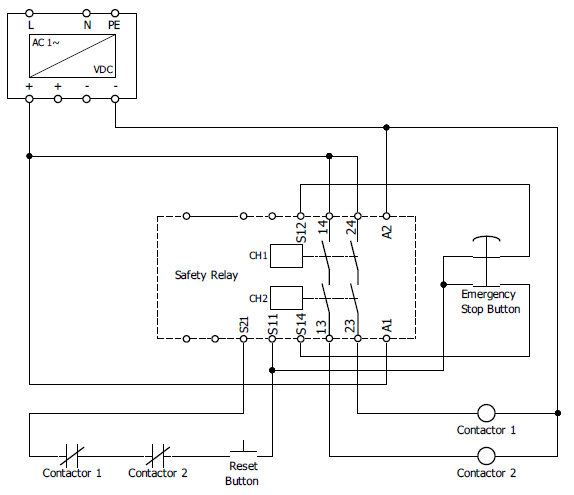
Several key points are worth noting regarding the electrical schematic above.
- Power—The safety relay and contactors are powered by a 24VDC power supply connected directly to the A1 and A2 terminals.
- The Emergency Stop Button (E-Stop)—Notice that the emergency stop button has two normally closed contacts that are mechanically connected. This is part of the redundancy-centric nature of safety systems. A pulsed signal from terminal S11 passes through both e-stop contacts before reaching terminals S12 and S14. When the E-Stop is depressed, both contacts are forced open, which cuts the signal to terminals S12 and S14.
- Safety Outputs—Terminals 14 and 24 are the input side of the safety outputs section of the safety relay. These two are connected directly to the power supply. When all safety conditions are met, the relay will close a set of force-guided* and redundant relays. This will send power to terminals 13 and 23, which will power the two contactors.
- Contactors—The safety outputs provide a dual-channel, redundant signal connected to two contactors. These contactors will then be connected in series to control a motor.
- Feedback Loop – The feedback loop monitors the contactors. In their normal state, a force-guided*, normally closed contact will inform the relay of faults within the contactor, such as welded or stuck contacts. The feedback loop monitors the contactors via their normally closed auxiliary contacts. Depending on the relay design, this may be a static monitored loop or may include test pulses for diagnostic checking. The two contacts are wired in series and returned to the safety relay on terminal S21.
- Reset Button—If the safety relay is tripped, this button resets the relay to its regular operation once all safety conditions are met. In this case, the signal passes through the contactor feedback loop.
*Force-guided: These types of contacts are designed to be mechanically connected and move together as a single unit. If a contact is stuck or welded, the other contacts will remain in place.
What kind of faults can safety relays detect?
How Does a Safety Relay Work?
A safety relay monitors a specific safety function or device, such as a light curtain. The safety relay will electronically evaluate inputs and control its outputs based on these evaluations.
Term: OSSD
OSSD Stands for Output Signal Switching Device. An electronic circuit sends out a unique pulse, recognized as a safety signal. OSSD signals prevent accidental or intentional bypassing of safety devices.
OSSD outputs are typically two 24 VDC channels with short, staggered low-going test pulses. The out-of-phase pulses form a coded pattern that lets the receiving safety relay or controller detect shorts to 24 V, shorts to 0 V, and cross-faults between channels.
Safety Relay Functions
On a basic level, the safety relay has one or more of the following functions:
- A safety relay will still carry out the stop function if an internal fault is detected, allowing the system to stop or shut down due to its built-in redundancy and self-monitoring capabilities. Furthermore, a restart is inhibited until the fault is cleared.
- The safety relay will monitor input faults, including conductor shorts, stuck contacts, and ground faults.
- It may have at least two inputs that receive signals from an OSSD or dry contacts, such as those found in an emergency stop button.
- Depending on the design, safety relays and connected devices may use test pulses on inputs and outputs to detect wiring faults such as shorts between conductors or to ground.
- A safety relay detects if dual-channel inputs change state simultaneously. This is to detect potentially failed contacts on an external safety device. Sometimes, a coded magnetic interlock that closes too slowly can cause the safety relay to indicate a fault because the two channels do not close simultaneously.
- It has at least two safety outputs, and many safety relays have more than two. These safety outputs use positively guided contacts to ensure that the contact sets move as a single unit.
- It allows monitoring of output devices, such as contactors. This is known as EDM (External Device Monitoring).
- To restore a safety relay to normal operating condition after a fault, it must be power-cycled or reset.
- A safety relay may have a built-in time delay or other functions such as speed or frequency monitoring.
- It provides electrical isolation between the safety devices and the power control circuit.
Proper Wiring is Important!
One crucial consideration is that for a safety relay to function as expected and reduce risk, it must be wired correctly. I have seen interlock switches wired to a safety relay’s A1/A2 power input terminals, effectively removing power from the device. Not only is this the wrong way to connect a safety relay, but you won’t achieve the PL/Cat that the relay is capable of. Effectively, you’re using an expensive safety relay as a simple $10 power relay.
A typical use of a safety relay is to interconnect a safety interlock switch mounted on a guard with the contactors that power a motor.
The safety relay checks and turns on the motor contactors when all safety conditions are met.
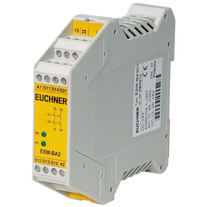
General Purpose Relay
This general-purpose safety relay can be used with our EOS4 light curtains, E-Stop buttons, or interlock switches.
Typical Applications & Usage Examples
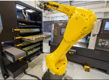
We commonly find safety relays in industrial environments, on machinery such as production lines, robots, and other devices that require a higher safety level and risk reduction.
Here are examples of standard safety devices that we can connect to the input terminals of a safety relay:
- Light curtains
- Safety Mats
- Two-hand button control
- Safety guarding interlocks
- Emergency stop buttons
On the output side of a safety relay, a standard connection is made to contactors, which, in turn, connect back to the safety relay’s inputs to monitor the contactors’ electrical contacts. In addition to contactors, we can connect a second safety relay or connect to special OSSD inputs on VFDs or drives.
Examples of machinery and equipment that make use of safety relays:
- Elevators
- Cranes
- Robots
- Stamping Presses
- Cutting Machines
- Printing Machinery
- Production Machinery
Relevant Standards
OSHA 1910.211(d)(62) – Safety system means the integrated total system, including the pertinent elements of the press, the controls, the safeguarding and any required supplemental safeguarding, and their interfaces with the operator, and the environment, designed, constructed and arranged to operate together as a unit, such that a single failure or single operating error will not cause injury to personnel due to the point of operation hazards.
ANSI B11.19 & ANSI B11.20 – Control Reliability
ISO 13849-1 – General principles for design, provides safety requirements and guidance on the principles of design and integration of safety-related parts of control systems (hardware or software).
IEC 62061 — Safety of machinery: Functional safety of safety-related control systems
IEC 61508 — Functional safety of electrical/electronic/programmable electronic safety-related systems
Further Reading
https://www.ferndalesafety.com/connecting-safety-interlock-switches-in-series/
https://www.ferndalesafety.com/two-hand-control-for-machine-safeguarding/
Practical Machinery Safety By David Macdonald
Your Next Step is Just a Call Away.
Ferndale Safety can help you with:
Fill out the form, and one of our safety experts will get in touch with you shortly.