Estimated reading time: 13 minutes
Safety guard interlock switches are used to protect workers from hazardous machine motion by ensuring the machine stops when a guard is opened or removed. These switches form part of the safety control system and are typically wired to remove power from the machine or trigger a safe state.
Wiring them correctly helps maintain worker safety, ensures compliance with standards like OSHA and ISO 14119, and prevents equipment damage. This guide walks you through the basics of how to wire them safely and effectively.
You Have a Safety Guard — Now What?
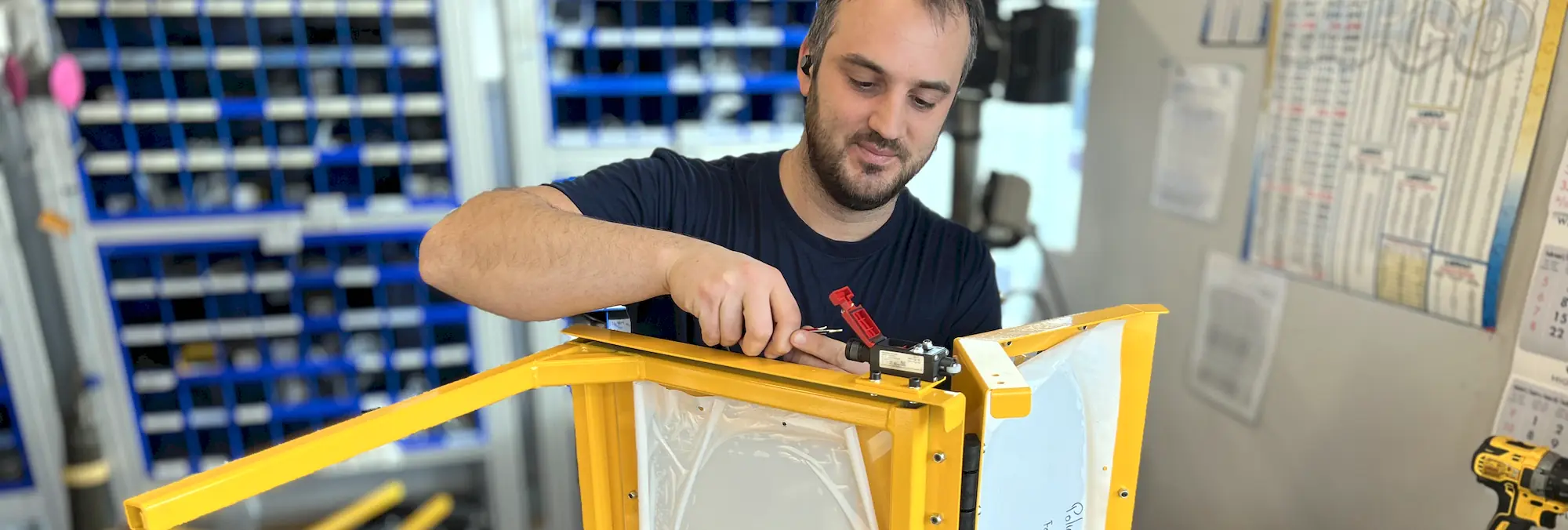
So, you’ve installed a machine safety guard equipped with an interlock switch. Great! That’s a big step toward protecting yourself and your team. But now comes the question: how do you wire it?
For many, the wiring part can feel overwhelming, especially if you’re not an electrician. But even some electricians who don’t have experience with safety systems may need a refresher. Don’t worry. This guide will break it down simply, without too much technical jargon. However, we will need to assume that you have a basic understanding of electricity and machine wiring.
IMPORTANT! Prioritize Safety First
Ensure that you lock-out-tag-out (LOTO)
Always De-energize and Lock Out Power. Before commencing any electrical work, it is of paramount importance to ensure the power is completely off and locked out. This critical step prevents accidental re-energization and protects against serious injury.
Wiring It Incorrectly Can Be Dangerous
If an interlock switch is wired incorrectly, it may fail to stop the machine, damage the switch, trigger false stops, cause unnecessary downtime, or, worse, lead to a safety incident.
Understanding how these switches work and how to wire them correctly is essential to making sure your guard system works as intended, maintaining worker safety, and ensuring compliance with standards.
Let’s go through the process step by step, using clear language and visual aids so you can wire your interlock switch with confidence.
What Is a Safety Guard Interlock Switch?
A safety guard interlock switch is a device designed to monitor the position of a machine guard and prevent the machine from running when the guard is open. Its primary purpose is to reduce the risk of injury and protect both workers and equipment during operation.
Some interlock switches also include guard locking features, which use electronic or electromagnetic mechanisms to physically prevent access to hazardous areas until the machine reaches a safe state. This added layer of protection helps ensure that guards cannot be bypassed or opened while dangerous motion is present.
Common Types of Interlock Switches
The two main categories of interlock switches are mechanical and non-contact. These range from basic plunger-style mechanical switches to more advanced safety devices equipped with electromagnetic guard locking, redundant circuits, feedback loops, and other sophisticated features.
While advanced interlock systems fall outside the scope of this guide, we’ll focus on the more commonly used types, including:
Plunger or Roller Switches (Mechanical): These are basic switches that activate when a plunger or roller is physically pressed. Of critical importance, you must install these switches correctly. That is to say, the switch must be connected in positive mode, where the switch plunger is only pushed in when the guard is open. You can read more about positive-mode actuation here.
Tongue/Key Switches (Mechanical): These engage when a key or tongue is inserted into the switch housing, often used with hinged or sliding guards. These multi-purpose safety interlock switches are often used on doors and covers, but have to be built solidly so the tongue and switch always align correctly. To prevent tampering, special screws are used to secure the key in place.
Hinged Switches (Mechanical): Mounted at pivot points, these switches activate when the guard is opened or moved.
Coded Magnetic Switches (Non-Contact): These use a magnetic field to detect when the guard is closed. In safety-rated models, the magnets are coded to prevent accidental or intentional bypassing. Magnetic switches consist of two parts: a sensor with a connection cable and an actuator containing the coded magnets.
RFID/Transponder-Coded Switches (Non-Contact): These contain built-in electronics and antennas that detect a specific radio signal from a paired actuator, offering higher security and resistance to tampering.
Most mechanical-type interlocks are contact-based, like those behind push-button switches. However, coded magnetic interlocks are also contact-based, but their contacts are tiny. Activating a contact-based switch closes or opens a contact, like how a light switch works. On the other hand, RFID interlocks use electronic circuitry to activate their outputs.
Watch out for current and voltage ratings.
The first step is to consult the interlock switch’s electrical datasheet. You’ll need to identify two key values: the maximum voltage and the maximum switching current the switch can safely handle.
Maximum Voltage (Volts)
This value depends on the type of switch. A mechanical switch, such as a plunger type, might be rated for up to 300 volts or more. In contrast, an RFID switch is typically rated for 24 volts. Connection of a voltage that is too high will result in switch failure.
Non-contact switches often fail when the wrong voltage is applied. For example, using high voltage on a coded magnetic switch can cause the small internal reed contacts to arc and weld together. This may result in the switch remaining permanently closed, creating a constant “on” state—even when the guard is open.
A Note About Higher Voltages
Specifically, voltages of 110 V or higher. While it is possible to wire interlock switches at this level, we strongly recommend using a 24-volt power source whenever feasible for increased safety and system compatibility.
If 24 volts is not an option, use extreme caution. Ensure all components are double-insulated, properly grounded, and rated for the operating voltage to prevent shock hazards. The power supply—such as a transformer—should have a neutral-to-ground connection and be protected with an appropriately rated fuse.
When in doubt, consult a licensed electrician or automation and control technician to review your setup and verify compliance with safety standards and local electrical codes.
Maximum Current (Amps)
This is the maximum amount of electrical current (in amps) that the switch can safely handle during operation. Mechanical switches may be rated for a few amps. In contrast, coded magnetic switches often have a much lower rating—typically around 0.25 amps (250 mA). What’s important to note is that most safety-rated interlocks are only intended to drive relay logic and not heavy loads, such as a motor.
Running more current than what a switch is rated for will most likely lead to the destructive failure of the switch.
The current running through the switch and its wiring entirely depends on what device it is connected to. A switch connected to a safety relay will draw much less than the same switch connected directly to a large contactor. Of course, it is vital to have the wiring fused according to local electrical standards.
Important
Never connect an interlock switch directly to a motor. The main reason is that motors draw far more current than most switches are rated to handle. For example, a small relay might draw only 0.25 amps, while a 115-volt, ½-horsepower motor can draw around 10 amps.
Another important reason is control: you don’t want the motor to start automatically just because the switch closes. We’ll cover this in more detail later.
Before You Start
Always conduct a formal machine risk assessment to determine the required performance level and category for any safety-related control systems.
Did you remember to lock out, tag out (LOTO)?
Simple connection of interlock switches
The simplest way to connect an interlock switch is to wire it in series with the stop or emergency stop circuit. This method only works if the machine is already equipped with a magnetic motor starter.
Conventional machines, such as milling machines and drill presses, might be wired this way to connect a simple chip shield.
Use this method only with mechanical switches unless you’ve performed a thorough current and voltage analysis of the machine’s control system. Non-contact switches typically have lower current ratings and may be damaged or fail if misconnected.
BEFORE
Electrical schematic of a typical motor control circuit. In this example, an emergency stop button and a stop button are in series. A start button is in parallel with a holding contact, which is connected in series with the contactor coil.
AFTER
We have added a safety interlock switch between the E-Stop and the Stop button. Notice that the interlock switch is a normally closed contact (positive action).
Auto-Restart
One of the most common mistakes in simple circuits is letting the machine auto-restart when the guard closes. Connecting the interlock switch to the wrong part of the circuit may produce unexpected results.
Test and ensure that the machine does not restart automatically when the safety guard and its interlock are closed.
Stop Category
Connection of an interlock switch directly to the stop circuit of a contactor is a Stop Category 0, which means that the power is immediately cut. There is no braking, and the machine coasts to a stop. Alternatively, a Stop Category 1 means that a controlled stop is performed, and then the power is cut.
Use in Safety Circuits
A series-wired interlock switch like this is considered a Category B safety circuit under ISO 13849-1, which defines it as the most basic level of safety architecture.
In the United States, ANSI classifies this as a simple safety circuit. However, it’s essential to understand the limitations: a single failure—such as a welded contact—could prevent the machine from stopping when the guard is open.
Warning About Use Cases
Don’t use this type of safety circuit in any application where the loss of safety function could lead to injury or death. A formal machine risk assessment is essential to determine the required performance level and category for any safety-related control system.
If the outcome of the risk assessment determines a higher performance level, then a simple Category B circuit will not be sufficient, and a safety relay with dual-channel monitoring becomes mandatory.
Furthermore, be wary when connecting safety interlock switches in series. While it is possible, connecting safety interlock switches in series can lead to fault masking, where a dangerous condition is hidden. In addition, series wiring multiple interlock switches cannot achieve higher safety ratings if required by a risk assessment.
Connection To Safety Relays
Most mechanical interlock switches can be connected to a safety relay if they are dual-channel and feature two normally closed (NC) contacts. These switches meet the typical requirements for safety relay input.
Coded magnetic, RFID, and transponder-based interlocks are also compatible with safety relays and can generally be connected without issue.
Keep in mind that wiring a safety relay involves more conductors than a basic two-wire Category B circuit. You’ll typically need separate lines for each channel, monitoring, and possibly feedback signals, depending on the safety relay’s configuration.
What’s so special about safety relays?
Unlike regular relays, we build safety relays to meet stringent safety standards, incorporating fail-safe principles that guarantee operational safety in critical conditions. A safety relay helps to check for losses in safety functions and detect internal failures, including faults with its inputs and outputs.
Want to know more about how to connect a safety relay, or just want to learn more about how they work? Check out our guide on how safety relays work by clicking here.
A typical Safety Relay Connection
A safety relay allows a higher safety category and performance level.
Conclusion
Wiring a safety interlock switch is more than just a technical exercise; it’s part of a larger system designed to protect people and equipment. A simple series connection might work in low-risk situations. Still, in most cases, a safety relay or more advanced architecture is needed to provide redundancy, diagnostics, and reliable stopping performance.
Always check the switch ratings, follow recognized standards such as ISO 13849-1, ISO 14119, and ANSI B11.19, and ensure a proper risk assessment is carried out before finalizing your design. By taking the time to connect interlocks correctly, you not only meet compliance requirements but also help create a safer, more dependable workplace.
Your Next Step is Just a Call Away.
Ferndale Safety can help you with:
On-Site Machine Safeguarding Assessments Discuss guarding options with you Design and manufacture custom guarding and enclosures
Fill out the form, and one of our safety experts will get in touch with you shortly.
Learn More About Machine-Specific Safety
We have more articles that may interest you on safeguarding specific types of machinery.
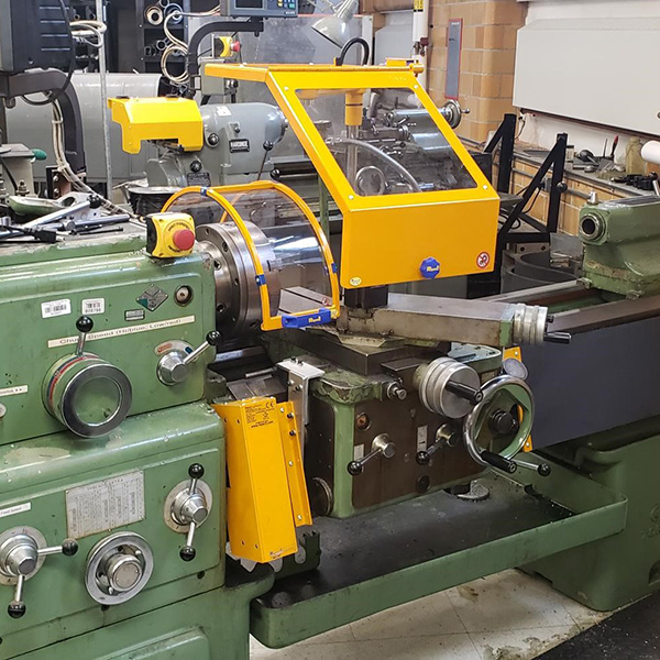
Find out how a lathe works and what can be done to increase lathe operator safety.
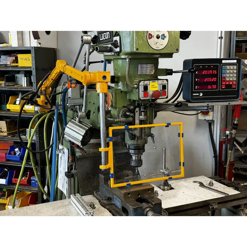
Learn about milling machines and how to safeguard them properly.
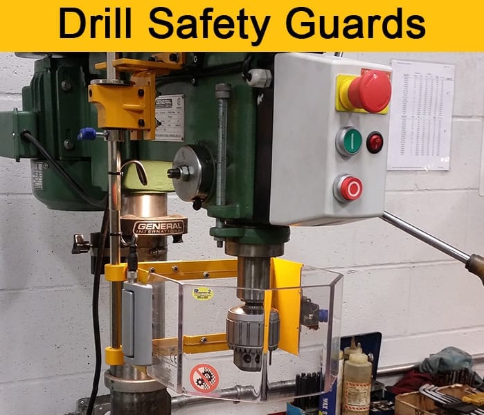
There is more to drill presses than you may think!
Did you know you should put anti-restart protection on your grinder?